


T: +86-18367823571
E: lyy@xg1688.cn
E: lyy@xg1688.cn
Building 2, No. 84, Qingxi Dongfeng Road, Qingxi Town, Dongguan City, Guangdong Province, 523642, China

Views: 0 Author: Site Editor Publish Time: 2026-01-09 Origin: Site
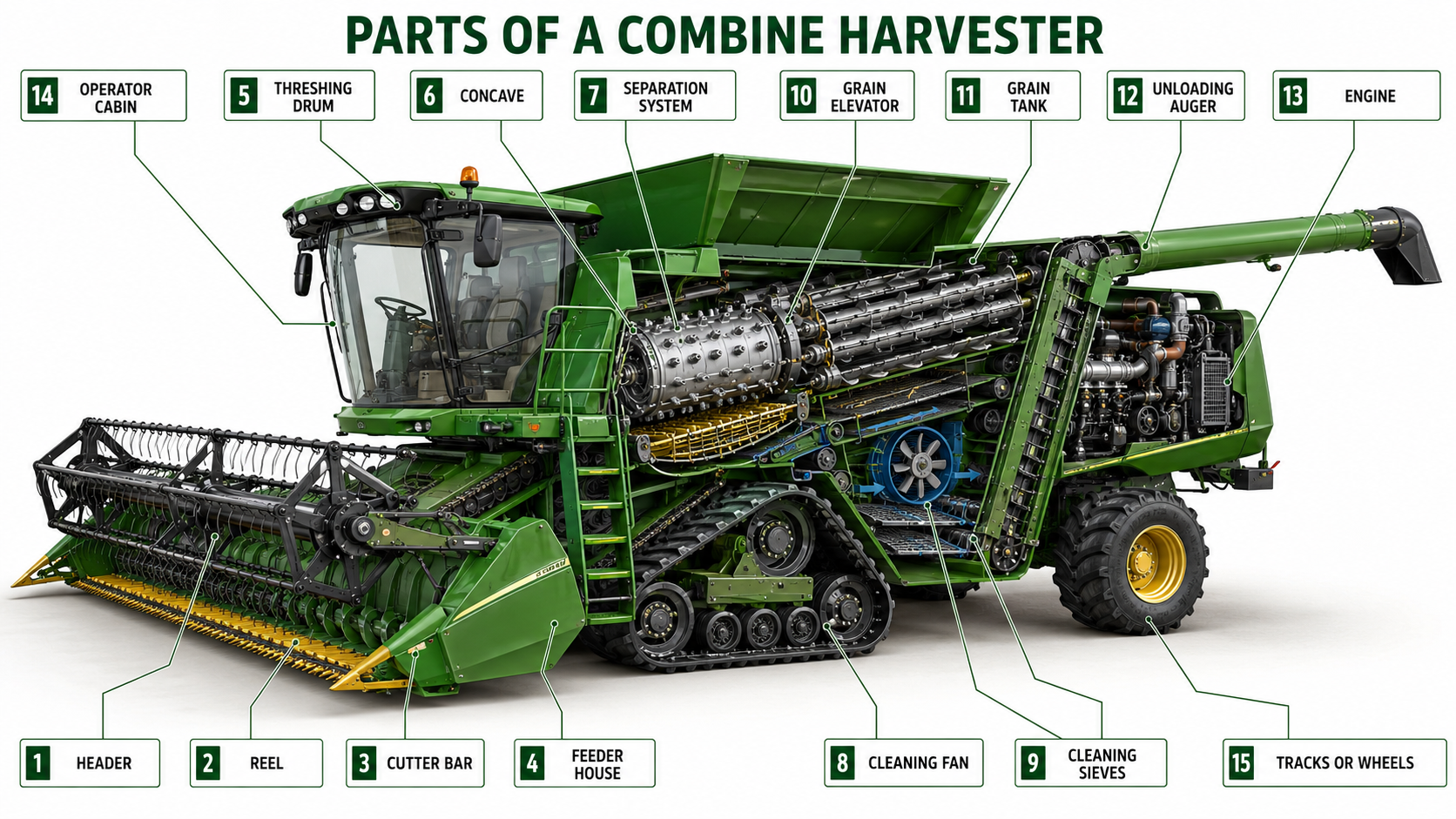
The main parts of a combine harvester include the header, reel, cutter bar, feeder house, threshing drum, concave, separation system, cleaning sieves, grain tank, unloading auger, engine and transmission. Each component performs a specific function, from cutting and gathering crops to separating, cleaning, storing and unloading grain. Understanding these combine harvester parts and their functions helps operators identify problems, make accurate adjustments, reduce grain loss and maintain efficient harvesting performance.
A combine harvester consists of several major systems that work together to cut crops, separate grain, remove impurities and store the harvested material. The principal combine harvester parts include the header, reel, cutter bar, feeder house, threshing drum, concave, separation system, cleaning fan, sieves, grain elevator, grain tank, unloading auger, engine, transmission and operator cabin.
The labeled diagram below shows where the main parts of a combine harvester are located.
| Combine Harvester Part | System | Main Function |
|---|---|---|
| Header | Crop Intake | Gathers standing crops and directs them into the machine |
| Reel | Crop Intake | Guides crops toward the cutter bar |
| Cutter Bar | Crop Intake | Cuts crop stems near ground level |
| Feeder House | Crop Feeding | Transfers harvested material into the threshing system |
| Threshing Drum or Rotor | Threshing | Separates grain from stalks, heads or pods |
| Concave | Threshing | Provides the surface and clearance needed for grain separation |
| Straw Walkers or Rotor | Separation | Recovers grain remaining in the straw |
| Cleaning Fan | Cleaning | Uses airflow to remove lightweight chaff |
| Upper and Lower Sieves | Cleaning | Separate clean grain from remaining impurities |
| Grain Elevator | Grain Handling | Transfers cleaned grain into the grain tank |
| Grain Tank | Grain Storage | Temporarily stores harvested grain |
| Unloading Auger | Grain Handling | Transfers grain from the tank into a trailer or truck |
| Engine | Power | Supplies power to the harvesting and drive systems |
| Transmission | Drive System | Controls machine movement and operating speed |
| Operator Cabin | Control | Allows the operator to control and monitor machine performance |
Each component has a specific role, but its design and operating settings may vary according to the combine harvester model, crop type and field conditions.
The crop intake system consists of the combine harvester parts responsible for cutting, gathering and transferring crops into the threshing system. Its principal components include the header, reel, cutter bar, header auger and feeder house. Correct selection, adjustment and maintenance of these components help maintain an even crop flow, prevent blockages and reduce harvesting losses.
The header is mounted at the front of the combine harvester and is the first component to contact the crop. Different header types are designed for different crops and field conditions.
| Header Type | Suitable Crops | Main Features |
|---|---|---|
| Grain Header | Wheat, barley, oats and rice | Uses a reel and cutter bar to cut and gather standing crops |
| Flex Header | Soybeans and low-growing crops | Follows uneven ground to reduce low-pod losses |
| Corn Header | Corn and maize | Uses row dividers and snapping rolls to separate ears from stalks |
| Draper Header | Wheat, canola and soybeans | Uses belts to deliver a smooth and consistent crop flow |
Choosing the correct header helps improve feeding consistency, reduce crop loss and match the combine harvester to specific harvesting requirements.
The reel rotates above the cutter bar and guides standing or lodged crops toward the cutting mechanism. Reel bats support the crop across the width of the header, while fingers or tines gently direct the stalks inward.
Reel height and speed should be adjusted according to crop height, density and field conditions. Incorrect adjustment may knock grain from mature plants, leave crops uncollected or cause uneven feeding.
The cutter bar cuts crop stems near ground level before the material enters the header. Its principal parts include reciprocating knife sections, guards, hold-down clips and drive components.
Sharp, correctly aligned knife sections help produce a clean cut and reduce plugging. Worn knives, damaged guards or incorrect clearance can leave uncut stalks, increase vibration and reduce harvesting efficiency.
After the crop is cut, the header auger moves the material toward the center of the header. Retractable fingers then guide it into the feeder house.
The feeder house uses a chain-and-slat conveyor to transfer crop material from the header to the threshing system. Correct chain tension and an even crop flow help prevent blockages, reduce component wear and maintain consistent threshing performance.
The threshing and separation system contains the combine harvester parts responsible for releasing grain from crop heads, stalks or pods and recovering grain remaining in the straw. Its primary components include the threshing drum or rotor, concave, straw walkers and rotary separators. Correct adjustment of these parts helps improve grain recovery while reducing broken kernels, unthreshed grain and unnecessary crop loss.
The threshing drum or rotor rotates against the concave to separate grain from harvested crop material through a combination of impact, friction and controlled pressure.
Conventional combine harvesters generally use a transverse threshing drum, while rotary combines use a longitudinal rotor that performs threshing and separation over a longer crop path. Drum or rotor speed must be adjusted according to crop type, grain moisture and field conditions.
Excessive speed may cause cracked or damaged grain, while insufficient speed can leave grain attached to the crop material.
The concave is a curved, grated component positioned beneath the threshing drum or rotor. As crop material passes through the space between these parts, separated grain falls through the concave openings and moves toward the cleaning system.
Concave clearance affects threshing intensity. A narrow clearance increases contact between the crop and threshing components, while a wider clearance provides gentler handling. The correct setting depends on crop type, maturity, moisture content and machine design.
Operators should follow the recommended settings for their specific combine harvester model rather than applying one fixed clearance to every crop.
After the initial threshing stage, some grain may remain mixed with the straw. The separation system recovers this remaining grain before the straw leaves the combine harvester.
| Separation Component | Main Function | Common Application |
|---|---|---|
| Straw Walkers | Shake and move straw while allowing remaining grain to fall through | Conventional combine harvesters |
| Rotary Separator | Uses rotating action to separate grain from crop residue | Rotary and hybrid combine harvesters |
| Separation Grates | Allow recovered grain to pass into the cleaning system | Used around rotors and separators |
Straw walkers can help preserve longer straw, while rotary separation systems generally provide a longer separation area and are commonly used for higher crop throughput. Actual performance depends on crop conditions, machine settings and combine design.
The cleaning system contains the combine harvester parts that remove chaff, straw fragments and other lightweight impurities from the separated grain. Its main components include the cleaning fan, upper sieve, lower sieve and tailings return system. These parts must work together with the correct airflow and sieve settings to produce clean grain while minimizing grain loss.
The upper and lower sieves separate grain from impurities according to particle size, weight and airflow response.
Upper Sieve or Chaffer: Removes larger pieces of chaff and crop residue while allowing grain to pass through.
Lower Sieve: Provides finer separation before clean grain enters the grain handling system.
Sieve openings should be adjusted according to the crop type, grain size, moisture level and harvesting conditions. Openings that are too wide may allow excess material into the grain tank, while openings that are too narrow can restrict grain flow and increase losses.
The cleaning fan directs a controlled stream of air through the sieves. This airflow lifts lighter chaff and residue away from the heavier grain.
Fan speed must be balanced with sieve openings and crop conditions. Insufficient airflow may leave excessive chaff in the grain sample, while excessive airflow can carry clean grain out of the machine. Operators should inspect the grain tank and material leaving the rear of the combine before making adjustments.
The tailings return system collects material that has not been fully separated during the first cleaning pass. It then returns this mixture for additional threshing or cleaning, depending on the combine harvester design.
A high tailings volume may indicate incorrect fan speed, unsuitable sieve openings, excessive crop loading or poor threshing adjustment. Regularly monitoring the tailings system helps operators identify problems before they reduce grain quality or harvesting capacity.
| Cleaning Problem | Possible Component Cause | Recommended Check |
|---|---|---|
| Excessive chaff in the grain tank | Low fan speed or wide sieve opening | Inspect airflow and sieve settings |
| Clean grain leaving with residue | Excessive fan speed or restricted sieve | Check grain loss and adjust gradually |
| High tailings volume | Incorrect sieve or threshing settings | Inspect sieves, fan and threshing system |
| Uneven grain cleaning | Blocked or damaged sieve | Clean and inspect the sieve surface |
After the cleaning system removes chaff and other impurities, the clean grain must be transferred, temporarily stored and unloaded without excessive damage or spillage. The main grain handling parts of a combine harvester include the clean grain auger, grain elevator, grain tank and unloading auger.
The clean grain auger collects grain from beneath the cleaning sieves and moves it toward the grain elevator. The elevator then lifts the grain and transfers it into the grain tank.
Depending on the combine design, the grain elevator may use a chain with paddles or another enclosed conveying mechanism. Worn paddles, loose chains, damaged housings or accumulated residue can reduce conveying capacity and increase grain damage.
Operators should regularly inspect the auger flighting, elevator chain tension, paddles and housing for wear or blockage.
The grain tank temporarily stores clean grain until it can be transferred to a trailer or truck. Its capacity varies significantly according to the size, design and intended application of the combine harvester.
Modern grain tanks may include level sensors, viewing windows, sample inspection points or monitoring displays that help operators track grain volume and quality. Grain should enter the tank evenly to prevent local overloading and maintain stable machine performance.
Operators should also inspect the grain tank for residue, corrosion, damaged sensors and loose covers before each harvesting season.
The unloading auger transfers grain from the grain tank into a trailer, truck or grain cart. It normally consists of an auger tube, rotating flighting, drive components and an adjustable discharge spout.
Smooth unloading depends on correctly maintained flighting, bearings, joints and drive mechanisms. Worn or damaged components may reduce unloading speed, cause vibration or result in grain leakage.
Before operating the unloading system, the operator should confirm that the auger is fully extended, the receiving vehicle is correctly positioned and the discharge area is clear.
| Grain Handling Part | Main Function | Common Inspection Point |
|---|---|---|
| Clean Grain Auger | Collects grain below the cleaning system | Flighting wear and blockage |
| Grain Elevator | Lifts clean grain into the grain tank | Chain tension, paddles and housing |
| Grain Tank | Temporarily stores harvested grain | Residue, sensors and covers |
| Unloading Auger | Transfers grain out of the grain tank | Flighting, bearings, joints and spout |
The engine and transmission components provide the power required to move the combine harvester and operate its cutting, feeding, threshing, separation, cleaning and grain handling systems. Engine output, transmission design and power distribution vary according to machine size, crop type, terrain and harvesting capacity.
Most modern combine harvesters use diesel engines designed to provide consistent power under changing crop loads and field conditions. The engine powers both the ground drive and the major harvesting components.
The required engine output depends on several factors, including header width, threshing system design, grain tank capacity, field terrain and expected crop throughput. Operators should refer to the specifications of the individual combine model rather than selecting a machine based on a general horsepower range.
Important engine inspection points include:
Engine oil and coolant levels
Fuel and air filters
Cooling system and radiator
Belts, hoses and electrical connections
Warning indicators and fault codes
Dust and crop residue around hot surfaces
Regular cleaning and maintenance help prevent overheating, power loss and unplanned downtime during harvest.
The ground drive system transfers engine power to the wheels or tracks and allows the operator to control travel speed. Combine harvesters may use mechanical, hydrostatic or electronically controlled drive systems, depending on the machine design.
| Transmission Type | Main Characteristics | Typical Benefit |
|---|---|---|
| Mechanical Drive | Uses gears and mechanical linkages | Simple structure and straightforward maintenance |
| Hydrostatic Drive | Uses hydraulic pressure to control travel speed | Smooth and precise speed adjustment |
| Electronically Controlled Drive | Integrates electronic controls with mechanical or hydraulic components | Improved operating control and automatic adjustment |
Hydrostatic ground drives are common on self-propelled combine harvesters because they allow operators to adjust travel speed without interrupting crop flow. However, the exact drive system should always be confirmed from the specifications of the individual machine.
A combine harvester uses a combination of belts, chains, shafts, gearboxes and hydraulic systems to distribute engine power to different components.
Belts and Chains: Drive headers, conveyors, threshing and cleaning components.
Shafts and Gearboxes: Transfer rotational power between major systems.
Hydraulic Systems: Operate steering, header height, reel position and other adjustable functions.
Overload Protection: Slip clutches, shear bolts or electronic monitoring may help protect components during blockages.
Loose belts, worn chains, damaged bearings or hydraulic leaks can reduce machine performance and cause unexpected downtime. These components should be inspected regularly and adjusted according to the manufacturer’s maintenance instructions.
| Power Component | Main Function | Common Inspection Point |
|---|---|---|
| Engine | Supplies power to the machine | Fluids, filters, cooling and warning indicators |
| Transmission | Controls machine movement | Oil level, response and unusual noise |
| Belts and Chains | Drive harvesting components | Wear, alignment and tension |
| Shafts and Gearboxes | Transfer rotational power | Lubrication, seals and vibration |
| Hydraulic System | Operates adjustable components | Fluid level, hoses and leakage |
The chassis and mobility components support the weight of the combine harvester, maintain stability and allow the machine to move safely across different field conditions. The main parts include the frame, steering system, axles, wheels or tracks and related suspension or tensioning components.
The chassis forms the structural foundation of the combine harvester. It supports the engine, threshing system, grain tank, operator cabin and other major components while withstanding vibration and changing field loads.
A stable chassis helps maintain component alignment and machine balance, particularly when the grain tank is full or the combine is operating on uneven terrain. Operators should inspect the frame for cracks, loose fasteners, corrosion and abnormal vibration as part of routine maintenance.
Combine harvesters may use wheels, tracks or a combination of both, depending on field conditions and machine design.
| Mobility Type | Best-Suited Conditions | Main Advantages | Inspection Points |
|---|---|---|---|
| Wheeled Combine | Dry, firm and relatively level fields | Higher travel speed and easier road movement | Tire pressure, tread wear, wheel bolts and axle condition |
| Tracked Combine | Wet, soft, muddy or uneven fields | Lower ground pressure, improved traction and reduced sinking | Track tension, rollers, sprockets and track wear |
| Front Tracks with Rear Wheels | Variable or soft field conditions | Combines front traction with conventional rear steering | Track system, rear tires and steering linkage |
The appropriate mobility system depends on soil conditions, crop type, field layout and operating requirements. Tracked combines are commonly selected for rice paddies and soft fields, while wheeled machines are generally more suitable for dry and firm ground.
The steering system allows the operator to control direction, complete headland turns and maintain alignment through crop rows. Depending on the combine design, steering may be hydraulic, electronically assisted or integrated with the machine’s ground drive system.
Important steering and mobility inspection points include:
Hydraulic hoses and fittings
Steering cylinders and linkages
Wheel alignment
Tire pressure or track tension
Axles, hubs and bearings
Unusual vibration or steering response
Any delayed response, fluid leakage, unusual noise or uneven movement should be inspected before continued operation.
The operator cabin contains the controls, instruments and monitoring components used to operate the combine harvester safely and efficiently. Depending on the machine model and configuration, the cabin may include mechanical controls, electronic displays, warning systems, cameras and precision farming functions.
The primary controls allow the operator to manage machine movement and adjust key harvesting components.
Common controls may include:
Steering and ground speed controls
Header lifting and lowering controls
Reel height and speed adjustment
Threshing drum or rotor speed adjustment
Concave clearance controls
Cleaning fan and sieve settings
Grain unloading controls
Emergency stop or shutdown functions
Control layout varies by combine harvester model. Operators should understand the function of each lever, switch and display before entering the field.
Monitoring systems help the operator identify changes in machine performance and respond before they cause grain loss, blockage or component damage.
| Monitoring Component | Main Function |
|---|---|
| Engine Display | Shows engine speed, temperature, fuel level and warning information |
| Grain Tank Indicator | Alerts the operator when the grain tank approaches capacity |
| Grain Loss Monitor | Helps identify excessive grain leaving the machine |
| Blockage Warning | Indicates restricted crop flow or overloaded components |
| Camera System | Improves visibility around the header, grain tank or unloading area |
| Warning Lights and Alarms | Notify the operator of abnormal operating conditions |
The availability and design of these monitoring components depend on the individual combine harvester configuration.
Some combine harvesters may be equipped with optional smart farming and automation features, including:
GPS or satellite-guided steering
Yield and moisture monitoring
Field mapping
Automatic header height control
Automatic adjustment of threshing and cleaning settings
Remote machine monitoring
Operating data recording
These functions can help improve driving accuracy, reduce overlap and support more consistent harvesting. However, they should only be presented as standard features when they are confirmed in the specifications of the relevant combine harvester model.
Regular inspection and maintenance help keep combine harvester parts operating reliably during the harvesting season. Worn cutting components, loose chains, blocked sieves or damaged bearings can reduce harvesting capacity, increase grain loss and lead to unexpected downtime.
Maintenance procedures and service intervals vary by machine model. Operators should always follow the instructions provided in the applicable operation and maintenance manual.
| Inspection Stage | Components to Check | Recommended Action |
|---|---|---|
| Before Operation | Engine fluids, belts, chains, tires or tracks | Check levels, wear, alignment and tension |
| Before Operation | Header, reel, cutter bar and guards | Inspect for damage, blockage and loose parts |
| During Operation | Threshing drum, concave and separation system | Monitor vibration, noise and grain quality |
| During Operation | Cleaning fan and sieves | Check cleaning performance and grain loss |
| After Operation | Feeder house, threshing and cleaning areas | Remove accumulated straw, chaff and dust |
| After Operation | Grain tank, elevators and unloading auger | Check for residue, leakage or blockage |
| Periodic Maintenance | Bearings, chains, shafts and gearboxes | Lubricate and inspect according to the manual |
| Periodic Maintenance | Hydraulic hoses and electrical connections | Check for leaks, wear and loose connections |
Common signs of component problems include unusual noise, excessive vibration, uneven feeding, poor grain quality, increased grain loss and reduced unloading speed. These symptoms should be investigated before they develop into more serious failures.
Combine harvester components may continue moving after the controls are disengaged. Before inspecting, cleaning or servicing any part of the machine:
Park the combine on stable, level ground whenever possible.
Disengage the header and other harvesting systems.
Stop the engine, remove the key and wait for all moving parts to stop.
Lower the header or secure it with the approved safety support.
Keep guards and protective covers correctly installed.
Never clear a blockage while the machine is running.
Keep hands, clothing and tools away from belts, chains, augers and rotating parts.
Follow the lockout and maintenance procedures provided for the specific machine.
Use suitable protective equipment when cleaning or servicing components.
Safety devices such as guards, interlocks, warning lights and emergency controls vary between combine harvester models. Their availability and operation should be confirmed from the specifications and manual of the individual machine.
The main parts of a combine harvester include the header, reel, cutter bar, feeder house, threshing drum or rotor, concave, separation system, cleaning fan, sieves, grain elevator, grain tank, unloading auger, engine, transmission and operator cabin.
Inside a combine harvester are the feeding, threshing, separation, cleaning and grain handling systems. Major internal components include the feeder conveyor, threshing drum or rotor, concave, straw walkers or separators, cleaning fan, sieves, grain augers and elevators.
A modern combine harvester contains hundreds of individual parts. These components are generally organized into major systems, including crop intake, feeding, threshing, separation, cleaning, grain handling, power transmission, mobility and operator control.
The header gathers the standing crop, the reel guides it toward the cutting mechanism, and the cutter bar cuts the stems. The header auger then moves the harvested material toward the feeder house.
The threshing drum or rotor and concave perform the initial grain separation. Straw walkers or rotary separators then recover grain that remains in the straw before the crop residue leaves the machine.
The cleaning fan uses airflow to remove lightweight chaff, while the upper and lower sieves separate grain from larger and smaller impurities. Correct airflow and sieve settings help produce clean grain while limiting grain loss.
The grain tank temporarily stores clean grain after it passes through the cleaning system. When the tank is ready to be emptied, the unloading auger transfers the grain into a trailer, truck or grain cart.
Different headers are designed for specific crops and field conditions. Grain headers are commonly used for wheat and other small grains, corn headers collect ears of corn, and flex headers follow uneven ground when harvesting soybeans and other low-growing crops. Selecting the correct header improves feeding and helps reduce crop loss.
Understanding the main parts of a combine harvester makes it easier to compare machines by cutting width, feeding capacity, threshing structure, grain handling system and field adaptability. The following models are designed for harvesting rice, wheat and other common grain crops.
| Combine Harvester Model | Harvester Type | Feeding Capacity | Cutting Width | Recommended For |
|---|---|---|---|---|
| 4LZ-6.0Z | Full-feed tracked combine harvester | 6.0 kg/s | 2,200 mm | Medium-capacity harvesting of multiple crops |
| 4LZ-4.0S / 4LL-2.0D | Full-feed tracked double-drum harvester | 4.0 kg/s | 2,000 mm | Farms requiring a double-drum threshing system |
| 4LZ-7.0Z | Full-feed tracked combine harvester | 7.0–8.0 kg/s | 2,360 mm | Higher-throughput grain harvesting |
Actual specifications and available configurations may vary according to crop conditions and market requirements. Contact Thinker Agricultural Machinery for model selection and configuration information.
The main parts of a combine harvester work together to cut, feed, thresh, separate, clean, store and unload grain. Key components include the header, reel, cutter bar, feeder house, threshing drum or rotor, concave, cleaning fan, sieves, grain elevator, grain tank and unloading auger.
Understanding these combine harvester parts and their functions helps operators select suitable equipment, identify performance problems and maintain the machine more effectively. However, component design and specifications may vary according to the crop, harvesting capacity and field conditions.
To understand how these components operate as a complete harvesting system, read our guide on how a combine harvester works. If you are comparing equipment, explore our combine harvester selection guide or view Thinker Agricultural Machinery’s available combine harvesters.
Need help choosing a combine harvester for your crops and field conditions? Contact Thinker Agricultural Machinery to discuss harvesting capacity, cutting width, threshing configuration and other equipment requirements.


